Operating System Learning Notes (8) I/O Management Subsystem
Overview
Due to the wide variety of I/O devices, the functions and transmission rates vary greatly, so the need for a variety of methods to control the device, these methods together constitute the operating system kernel I/O subsystem, it will be the other aspects of the kernel from the heavy I/O Facility Management freed.
The main services provided by the I/O core subsystem are:
- I/O Dispatching
- Buffering and Cache
- Equipment distribution and recycling
- Spooled
- Equipment protection
- Error handling
I/O scheduling
The order of system calls issued by applications is not necessarily the best choice, so I/O scheduling is needed to improve overall system performance, so that device access is fairly shared between processes, and the average latency required for I/O is reduced.
Operating system developers implement scheduling by maintaining a request queue for each device. When an application executes a blocking I/O system call, requests are added to the queue of the corresponding device.
I/O scheduling rearranges scheduling order to improve overall system efficiency and the average response time of applications.
The I/O subsystem can also use storage space techniques on main memory or disk, such as buffering, caching, spooling, etc., to improve computer efficiency
Disk scheduling algorithm is a kind of I/O scheduling.
Cache and buffer
Disk cache
The operating system uses disk caching technology to improve disk I/O speed, and the access to cache replication is faster than the original data source access. For example, running process instructions are stored both on disk and in physical memory, and are also copied to the CPU’s second-level and first-level caches.
However, the disk cache is different from the usual sense of a small-capacity high-speed memory between the CPU and the memory, but refers to the use of memory storage space to temporarily store information in a series of disk blocks read out from the disk.
Therefore, the disk cache belongs to the disk logically, and is a disk block that resides in memory physically.
Cache is divided into two forms in memory.
One is to open up a separate piece of storage space in memory as a disk cache, with a fixed size;
The other is to use the unused Memory Space as a buffer pool for the request paging system and disk I/O to share.
Buffer zone
In the Facility Management subsystem, the main purpose of introducing buffers is as follows:
- Mitigate speed mismatch between CPU and I/O devices.
- Reduce CPU interrupt frequency and relax restrictions on CPU interrupt response time.
- Resolve basic data unit size mismatch issue
Improve parallelism between CPU and I/O devices
This is achieved as follows:
- The use of hardware buffers, but the cost is too high, only in some key parts of the use.
- Using buffer (in memory)
Buffer has a feature, that is, when the buffer data is not empty, it cannot be flushed into the data like the buffer, and can only read data from the buffer. When the buffer is empty, you can flush data into the buffer, but you must fill the buffer before you can read data from it.
According to the number of buffers set by the system, the buffering technology can be divided into the following types:
Single buffer
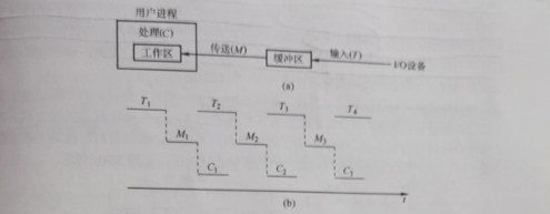
A buffer is provided between the device and the processor. When the device and the processor exchange data, the exchanged data is first written into the buffer, and then the device or processor that needs the data removes the data from it.
When the block device input, it is assumed that a piece of data from the disk input buffer time T, the operating system to remove data from the time M, CPU processing time of this piece of data is C.
When we study the time for each piece of data to be processed by various buffering techniques, we assume an initial state, and then calculate the time to reach the same state next time, which is the time to process a piece of data (if not explicitly stated, it is generally considered that the buffer size is the same as the workspace).
We assume that T > C, the initial state workspace is full and the buffer is empty.
When the workspace has finished processing the data, the time is C, but the buffer is not yet full.
Wait until the buffer is full, from time T, stop flushing data.
Then the data from the buffer into the work area, with M, when the work area is full, the buffer is empty, to the next state, this brother process with M + T.
If T < C, similarly, the time is M + C
Therefore, the time for single-buffer processing of each piece of data is max (C, T) + M.

Double buffering
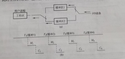
According to the single buffering feature, the CPU is idle during the transmission time M, thereby introducing double buffering
We assume that the initial state is that the workspace is empty, where one buffer is full and the other is empty, and can be calculated again.
We divide the discussion into two cases: T < M + C and T > M + C.
The conclusion is that the time for double buffering to process a piece of data is max (C + M, T).

If T > M + C, we can use the block device for continuous input; if T < M + C, we can make the CPU not have to wait for device input.
For character devices, if line input is used, double buffering may be used after the user inputs the first line, when the CPU executes the first line command, the user may input the next line of data to the second buffer.
If only a single buffer is set between two machines, they can only achieve one-way data transmission at any time. In order to achieve bidirectional data transmission, another buffer must be set, one as the send buffer and the other as the receive buffer.
Cyclic buffering
Contains multiple buffers of the same size, each buffer has a linked pointer to the next buffer, the last buffer points to the first buffer, and multiple buffers form a ring.
When the circular buffer is used for input and output, two pointers in and out are also required. For input, data is first received from the device into the buffer, with the in pointer pointing to the first empty buffer where data can be input and the out pointer pointing to the first full buffer where data can be extracted. Output is the opposite (?).
Buffer pool
It consists of buffers common to multiple systems. Buffers can be divided into three queues according to their usage.
- Empty buffer queue
- Buffer queue filled with input data (input queue)
- Buffer queue full of output data (output queue)
There should also be four types of buffers:
- Working buffer for holding input data
- Working buffer for extracting input data
- Working buffer for holding output data
- Working buffer for extracting output data
When the input process needs to input data, an empty buffer is removed from the head of the empty buffer queue as a working buffer for accommodating input, and then input data into it, and then hang to the end of the input queue after being filled.
When the calculation process needs to input data, a buffer is obtained from the input queue as a working buffer for extracting input data, and the empty buffer queue is returned to the end of the queue after the extraction is completed.
Comparison of cache and buffer

Equipment distribution and recycling
Equipment distribution overview
Device allocation refers to the allocation of the required equipment according to the user’s I/O requests. The general principle of allocation is to give full play to the efficiency of the equipment, keep the equipment as busy as possible, and avoid process deadlock caused by unreasonable allocation methods.
From the perspective of device characteristics, devices using the following three usage methods are called exclusive devices, shared devices, and virtual devices.
- Exclusive use of equipment
- Time-sharing devices, such as disk I/O, each I/O operation request of each process can be alternated through time-sharing
- Use external devices in the SPOOLing way. This technology was introduced in the era of batch processing operating systems, that is, spooled I/O technology. The operation of this technology on the device is actually batch processing of I/O operations, which is a space-for-time technology.
Data structure for device allocation
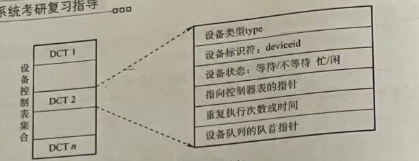
The main data structures based on device allocation are device control table (DCT), controller control table (COCT), channel control table (CHCT) and system device table (SDT).
Device Control Table (DCT): We can think that a device control table symbolizes a device, and the entry of this control table is the various properties of the device. As shown in Figure

We have learned four kinds of I/O control methods before, and the channel mode is obviously superior to other methods. Therefore, the I/O control of modern operating systems adopts channel control.
The device controller controls the exchange of data between the device and the memory, and the device controller needs to request the channel to serve it, so each COCT must have a table entry to store a pointer to the corresponding channel control table (CHCT), and a channel can be used for multiple Device controller services, so there must be a pointer in CHCT pointing to a table, and the information on this table expresses the device controllers that CHCT provides services. The relationship between CHCT and COCT is a one-to-many relationship.
System Device Table (SDT): There is only one SDT in the entire system, which records the situation of all physical devices connected to the system, and each physical device occupies an entry.

Since the number of processes is more than the number of resources in a multiprogram system, it will cause competition for resources, so there must be a set of reasonable allocation principles. The main considerations are: the inherent properties of I/O devices, the allocation of I/O devices algorithm, the security of I/O device allocation, and the independence of I/O devices.
Device allocation strategy
- Equipment allocation principle. Equipment allocation should be based on equipment characteristics, user requirements and system configuration. The general principle of allocation is: not only to give full play to the efficiency of the equipment, but also to avoid causing process deadlock. It is also necessary to isolate user programs from specific devices.
- Device allocation method. There are two types: static allocation and dynamic allocation.
Static allocation is mainly used for the allocation of exclusive devices. It allocates all the devices, controllers (such as channels, etc.) required by the job at one time before the user’s job starts to execute. Once allocated, these devices, controllers (and channels) remain owned by the job until the job is revoked. Static allocation does not deadlock, but is inefficient and does not meet the general principle.
Dynamic allocation is allocated according to needs during the execution of the process, and dynamic allocation requires appropriate allocation algorithms.
- Device allocation algorithm. Common dynamic device allocation algorithm has first request first allocation, higher priority and so on.
Here you can contact the critical quota in process scheduling, how to avoid deadlock, such as banker algorithm?
Security of device allocation
Refers to the fact that deadlocks should be avoided during equipment allocation
- Safe allocation method. Every time a process issues an I/O request, it enters a blocking state and is not woken up until other I/O operations are completed. In this way, once a process obtains a certain device, it is blocked and cannot request any resources, and it is blocked. No resources are kept. The advantage is that device allocation is safe, but CPU and I/O are serial (for the same process).
- Unsafe allocation method. The process continues to run after issuing an I/O request, and issues a second or third I/O request when needed. It only enters a blocking state when the device requested by the process is already occupied by another process. The advantage is that multiple devices can be operated at the same time, thus advancing the process quickly. The disadvantage is that there may be deadlocks (because resources are not released when entering a block).
Logical device name to physical device name mapping
In order to improve the flexibility of device allocation and device utilization, and facilitate the realization of I/O Retargeting, device independence is introduced. It refers to the independence of the application from the specific physical device used.
In order to achieve device independence, logical device names are used in the application to request the use of certain types of devices.
Set up a Logic Unit Table (LUT) in the system to map logical device names to physical device names. The LUT table entry includes logical device names, physical device names, and device driver entry addresses.
When the process requests the allocation device with a logical device, the system assigns the corresponding physical device to it, and establishes a table entry in the LUT. After the process uses the logical device name to request the I/O operating system, the system finds the corresponding LUT by looking up the corresponding physical device and driver.
There are two ways to create a LUT:
- Set only one LUT in the entire system. Mainly suitable for single-user systems
- One LUT per user. When a user logs in, the system creates a process and a LUT for the user, and stores the LUT in the PCB of the process.
SPOOLing technology (spooler technology)
In order to alleviate the contradiction between the high speed of CPU and the low speed of I/O devices, offline I/O technology is introduced.
This technology utilizes specialized peripheral controllers to transfer data from low-speed I/O devices to high-speed disks, or vice versa.
SPOOLing means that external devices operate online at the same time, also known as spooled input/output operation, which is a technology used in the operating system to transform an exclusive device into a shared device.

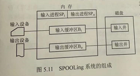
- Input and output wells
An input well and an output well refer to two storage areas opened up on a disk. The input well simulates the disk when the offline input is used to house the data input by the I/O device. The output well simulates the disk when the offline output is used to house the output data of the user program.
- Input buffer and output buffer
Are two buffers created in memory. The input buffer is used to temporarily store data sent by the input device and then sent to the input well. The output buffer is used to temporarily store data sent from the output well and then sent to the output device.
- Input process and output process
The input process simulates offline input. It is a peripheral control machine that sends the data requested by the user from the input machine through the input buffer to the input well. When the CPU needs input data, it directly reads the data from the input well into memory.
The output process simulates the peripheral control machine when the output is offline, and sends the data required by the user to the output well from the memory first. When the output device is idle, the data in the output well is sent to the output device through the output buffer
Why go from the input machine to the input buffer (memory) to the input well (disk), and then read the memory from the disk when the CPU needs it, and go around?
In order that the CPU may not currently need this data, enter it in advance, okay?
Shared printers are an example of the use of SPOOLing technology, which has been widely used in multi-user systems and local area networks. When a user process requests print output, the SPOOLing system agrees to print, but instead of immediately assigning the printer to the user process, it does two things for it.
- The output process requests a free disk block for it in the output well and sends the data to be printed
- The output process then applies for a blank user request print table for the user process, fills in the user’s print request, and then hangs the table in the request print queue.