Computer Composition (1) Computer Overview
The performance of a computer system is largely characterized by the efficiency and role of software, and the performance of software cannot be achieved without the support of hardware. For a certain function, it can be implemented in software or hardware, which is called software and hardware is logically equivalent. When designing a computer system, the functions of software and hardware should be assigned. Generally speaking, if a function is frequently used and the cost of implementing it with hardware is ideal, hardware should be used to implement it, because the efficiency of hardware implementation is generally higher.
Computer hardware
Basic ideas of von neumann
When von Neumann studied EDVAC, he proposed the concept of “stored program”. The idea of “stored program” laid the basic structure of modern operating systems, and all kinds of computers based on this concept are collectively referred to as von Neumann machines. Its characteristics are as follows:
- Adopt the working method of “stored program”.
- The computer hardware system consists of five components: arithmetic unit, controller, memory, input device and output device.
Instructions and data are stored in memory in the same position, with no difference in form, while computers can distinguish them by relying on different stages of the instruction cycle. - Instructions and data are represented in binary. Instructions consist of operation codes and address codes. The operation code indicates the type of operation, and the address code indicates the address of the operand.
The basic idea of “stored program” is that the pre-prepared program and the original data source can be sent to main memory before execution. Once the program is started and executed, there is no need for operator intervention.
Its basic working mode is: control flow driven mode.
Functional components of a computer
Input device
The main function of an input device is to input programs and data into a computer in the form of information that the machine can recognize and accept. The most commonly used and basic input device is the keyboard.
Output device
The main task of an output device is to output the results of computer processing in a form acceptable to people or in the form of information required by other systems. The most common and commonly used output devices are monitors, printers, etc.
Storage
Memory is divided into main memory (also known as internal memory) and auxiliary memory (also known as external memory). The memory that the CPU can directly access is main memory. Secondary memory is used to help main memory remember more information. Information in secondary memory must be transferred to main memory before it can be accessed by the CPU.
The working mode of main memory is to access the address of the storage unit, which is called address access.

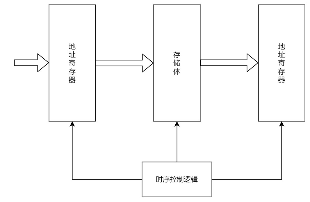
The most basic composition of main memory is shown in the figure.
The memory stores binary data, the address register (MAR) stores the memory access address, and finds the corresponding memory cell after address decoding.
The Data Register (MDR) is used to temporarily store information to be read or written from memory.
The timing control logic is used to produce various timing signals required for memory operation.
A memory bank consists of many storage units, each storage unit contains several storage elements, and each storage element stores one bit of binary code. Therefore, the storage unit can store a string of binary code, which is called a storage word. The storage length of this string of code is the storage word length, which needs to be an integer multiple of 1B (8bits).
What we usually call a 32-bit machine refers to the word length, also known as the machine word length. The so-called word length usually refers to the width of the data path used for integer operations inside the CPU, that is, the number of bits of binary data that can be processed by a computer for an integer operation (that is, fixed-point integer operation, this concept will be discussed later in the chapter), usually related to the number of registers and adders of the CPU. Therefore, the word length is generally equal to the size of the internal register. The longer the word length, the larger the data representation range and the higher the calculation accuracy.
The concept of word length is different from that of word. A word is used to represent the unit of information to be processed and is used to measure the width of a data type. For example, x86 defines a word as 16 bits.
Instruction word length: The number of bits of binary code contained in an instruction word.
Storage word length: The number of bits of binary code stored in a storage unit.
They must all be integer multiples of bytes.
The instruction word usually takes an integer multiple of the storage word length. If the instruction word length is equal to 2 times the storage word length, two memory access cycles are required to retrieve an instruction. If the instruction word length is equal to the storage word length, the instruction fetch cycle is equal to the machine cycle.
MAR for addressing, the number of bits corresponding to the number of memory cells, such as MAR bit 10, there are 2 ^ 10 = 1024 memory cells, that is, 1k, the information that can be stored is 1k * storage word length.
The virtual address should not be considered here, and the physical address that goes to the MAR is already converted.
The length of the MAR is the same as the length of the PC, and both are used to store addresses. It’s just that the content in the memory pointed to by the address stored by the PC must be an instruction.
The length of MDR is equal to the storage word length, usually an integer multiple of the second power of the byte. Because the role of MDR is to temporarily store the content to be read or written from memory, in general, the length of each read and write from memory is one storage word length.
So * should the constant of the data bus be the same as the length of the MDR? *
Note that although MAR and MDR are part of the memory, modern computers generally incorporate them into the CPU.
Arithmetic unit
An arithmetic unit is an executive part of a computer that performs arithmetic and logical operations.
The core of the arithmetic unit is the Arithmetic and Logic Unit (ALU). The arithmetic unit contains several general purpose registers for staging operands and intermediate results, such as the accumulator (ACC), multiplier quotient register (MQ), operand register (X), index register (IX), base address register (BR), etc., the first three registers are required.
There is also a program status register (PSW) inside the arithmetic unit, also known as the flag register, which is used to store some flag information obtained by the ALU operation or the status information of the processor, such as whether the result is overflowing, whether there is a carry or offset, etc.
Controller
The controller is the command center of the computer, which directs the various components to work automatically and harmoniously.
The controller consists of a Program Counter (PC), an Instruction Register (IR), and a Control Unit (CU).
PC is used to store the address of the current instruction to be executed, and can automatically add 1 to form the address of the next instruction, and there is a direct path between it and the main memory MAR.
IR is used to store the current instruction, and its content comes from the MDR of main memory. The OP (IR) in the instruction is sent to the CU for analyzing the instruction and issuing various micro-operation command sequences; while the address code Ad (IR) is sent to the MAR for fetching the operands.
As mentioned above, the instruction word length can be an integer multiple of the storage word length, so the length of the IR can be an integer multiple of the MDR, that is, an instruction may be fetched multiple times.
Generally, the arithmetic unit and controller are integrated into the same chip, called the Central Processor.
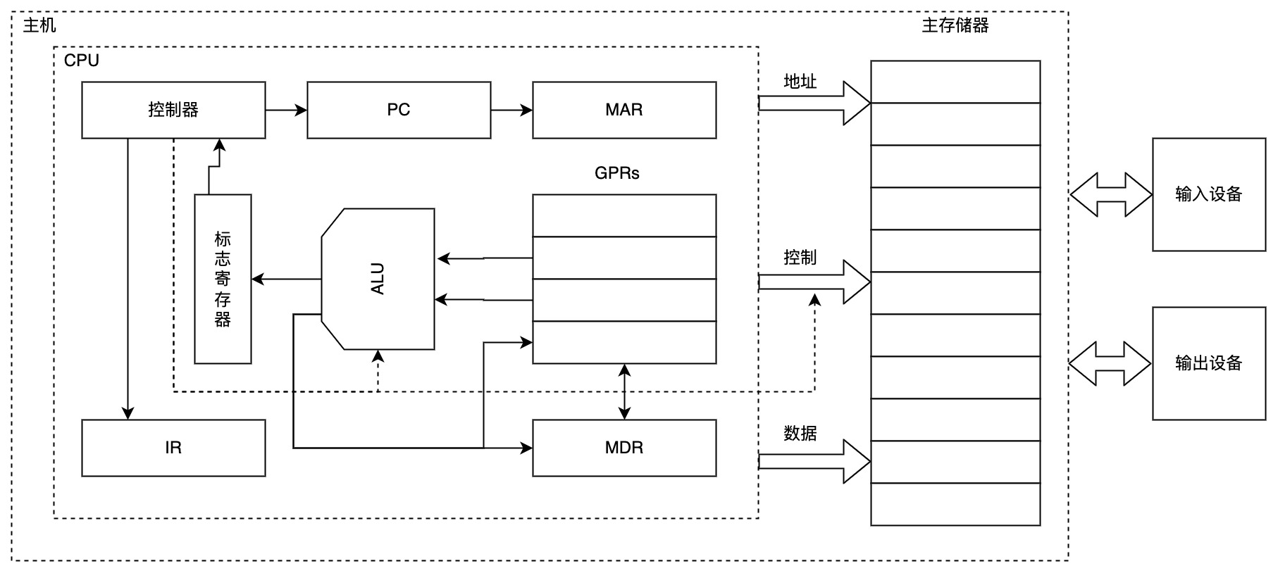
CPU contains ALU, general purpose register group GPRs, PSW, controller, IR, PC, MAR, MDR, etc.

The above figure is a simple architecture diagram of a CPU. Through the above figure, we simply analyze the execution process of the next instruction:
- The address of the next instruction is indicated in the PC register and placed on the address bus through the MAR.
- The controller issues a read command to the control bus.
- According to the address indicated by the address bus, obtain instructions from main memory and place them on the data bus.
- Because the control bus indicates that it is now a read command, read instructions from the data bus into the MDR and then into the IR
- IR put the OP (opcode) into the CU to parse, then put the Ad (address code) into the MAR, then get the data from memory, put it in the MDR, and then put the data into GPRs.
- If the instruction parses successfully, the data is also placed in the general purpose register, and the ALU can be used for calculation.
Computer software
System software and application software
System software is a set of basic software that ensures the efficient and correct operation of a computer system, usually provided to users as system resources.
The system software mainly includes operating system, database management system (DBMS), language processing system, distributed software system, network software system, standard library program, service program, etc.
Application software refers to programs developed for users to solve various problems in an Application Area.
Three levels of language
- Machine language
- Assembly language
- High level language
Due to the inability of computers to directly understand and execute high-level languages, programs that need to convert high-level languages into machine language are usually called translation programs. Translation programs are divided into three categories:
- Assembly program (assembler). Translate assembly language into machine language.
- Interpreter (interpreter). Translate the statements in the source program into its instructions one by one in the order of execution and execute them immediately.
- compile program (compiler). Translate high-level language into assembly language or machine language.
The interpreter does not generate a fully translated program in memory.
Logical functional equivalence of software and hardware
Hardware often implements the most basic arithmetic and logic functions, while most other functions are augmented by software.
For a certain function, it can be implemented by both hardware and software. From the user’s point of view, they are functionally equivalent, which is called functional equivalence of software and hardware logic.
Equivalence is an important basis for computer system design. When designing a computer system, we must consider whether a certain function is implemented in hardware or software from many aspects.
Hierarchical structure of computer systems

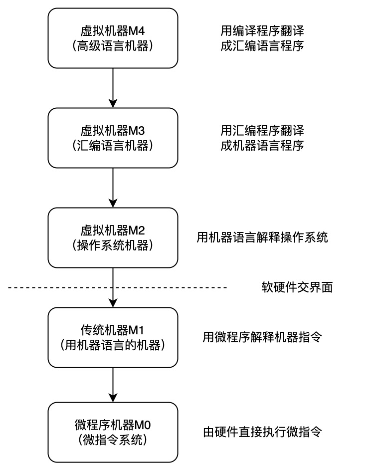
Level 1 is the microprogrammed machine layer, which is a real hardware layer that executes microinstructions directly from the machine hardware.
The relationship between machine instructions and microinstructions can be summarized as follows:
A machine instruction corresponds to a microprogram, which is composed of several microinstructions. Therefore, the function of a machine instruction is realized by a sequence composed of several microinstructions. In short, the operation completed by a machine instruction is divided into several microinstructions to complete, which are interpreted and executed by microinstructions.
From the one-to-one correspondence between instructions and microinstructions, programs and microprograms, and addresses and microaddresses, the former is related to internal memory, while the latter is related to control memory (which is a part of the microprogram controller. The microprogram controller is mainly composed of three parts: control memory, microinstruction register and address transfer logic. Among them, the microinstruction register is further divided into two parts: the microaddress register and the microcommand register), and there are corresponding hard devices related to this.
It can be seen from the flowchart of microprogram execution of general instructions. Each CPU cycle is for one microinstruction. This tells us how to design microprograms, and will also allow us to further experience the relationship between machine instructions and microinstructions.
Level 2 is the traditional machine language layer, which is also an actual machine layer with microprograms interpreting machine instruction systems.
- Level 3 is the operating system layer, which is implemented by operating system programs, which are composed of machine instructions and generalized instructions. These generalized instructions are software instructions defined and interpreted by the operating system for the purpose of extending machine functions, so this layer is also called the hybrid layer.
The specific content of generalized instructions can be delved into when looking at the operating system.
- The fourth layer is the assembly language layer, which provides users with a symbolic language through which assembly language programs can be written. This layer is supported and executed by the assembly program.
- Level 5 is the high-level language layer, which is user-oriented and set up for the convenience of users writing applications. This layer has support and execution of high-level program compilers.
Above the high-level language layer, there can also be an application layer.
Your pure hardware system without soft armor is called bare metal. Layers 3-5 are called virtual machines, which are simply software-implemented machines.
The relationship between the layers is close, the lower layer is the foundation of the upper layer, and the upper layer is the extension of the lower layer.
The working principle of computer system
How “stored program” works
This method stipulates that before the program is executed, the instructions or data contained in the program need to be sent to main memory. Once the program is started and executed, there is no need for operator intervention, and the extraction and execution tasks of the instructions are automatically completed one by one.
The execution process of each instruction includes: accessing the instruction from the main, decoding the instruction, calculating the address of the next instruction, taking the operand and executing it, and sending the execution result back to memory.
The instructions here are the machine instructions mentioned above. They are divided into multiple steps, and each step is called a microinstruction.
The time to fetch instructions is generally called a machine cycle, also known as a CPU cycle
From source program to executable file
When writing C language programs in a computer, they must be converted into a series of low-level machine instructions, packaged in a format called an executable object file, and stored as binary disk files.
Take GCC for UNIX as an example:

- Preprocessing stage: The preprocessor (cpp) processes commands starting with #in the source program, such as inserting the contents of the .h file after the #include command into the program file. The output is a source program with an extension of .i.
- compile stage: The compiler (ccl) compiles the preprocessed source program to generate an assembly language source program hello.s. Each statement in the assembly language source program describes a low-level machine language instruction in a text format.
- Assembly stage: The assembler (as) translates hello.s into machine language instructions and packages these instructions into a binary file called hello.s, which is a relocatable object file.
Link phase: The linker (ld) merges multiple relocatable object files and standard library functions into a single executable object file, or executable for short.
Description of program execution process
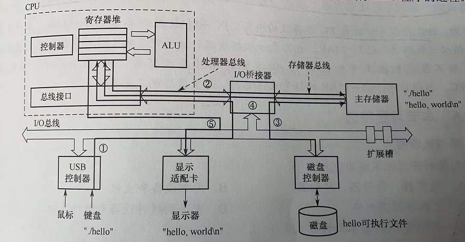
In UNIX, we can execute the program through the shell command line interpreter. The process of executing the program is explained through the shell command line as follows:
1 | ./hello |

The shell program reads each character entered by the user from the keyboard into the CPU register one by one (corresponding to 1), then saves it to the main memory, and forms the string “./hello” (corresponding to 2) in the buffer of the main memory. After receiving Enter, the shell calls up the kernel program of the system, and the kernel loads the executable file hello on the disk to the main memory (corresponding to 3). The kernel loads the code and data in the executable file (here is the string "hello, world! \ N "), the address of the first instruction of hello is sent to the PC, and the CPU then starts executing the hello program, which accesses each character in the string loaded into the main memory from the main memory to the CPU’s register (corresponding to 4), and then sends the characters in the CPU register to the display (corresponding to 5).
It is not so simple to send it directly to the PC here, it will involve the switching of processes.
Description of the instruction execution process
The code segment of the executable file is composed of a sequence of machine instructions represented by 0 and 1, which are used to indicate that the CPU completes a specific atomic operation.
For example, the number fetch instruction takes out a data from the storage unit and sends it to the register of the CPU. The number store instruction writes the contents of the register into a storage unit. The ALU instruction sends the contents of the two registers to some arithmetic or logical operation. In a CPU register. Taking the number fetch instruction as an example, it is sent to the ACC after fetching. The information flow is:
- Instruction fetch: PC - > MAR - > M -MDR - > IR
- Analysis instruction: OP (IR) - > CU
- Execute command: Ad (IR) - > MAR - > M - > MDR -ACC
Computer performance indicators
Word length
This has been mentioned earlier, you can take a look at the previous content.
Data path bandwidth (data word length)
Refers to the number of bits of information that the data bus can transmit in parallel at one time. The data path width mentioned here refers to the width of the external data bus, which may be different from the width of the data bus (internal register size) inside the CPU
Main memory capacity
Refers to the maximum capacity of the main memory can store information, usually measured in bytes, can also be used to express the storage capacity of the word * word length (such as 512K * 16 bits).
The number of bits in the MAR reflects the maximum addressable range and is not necessarily the actual memory capacity.
If the MAR length is 16 bits, it means that there are 2 ^ 16 = 65536 memory cells, which is 64K. If the MDR is 32 bits, it means that the storage word length is 32 bits, and the storage capacity is 64K * 32b.
Operation speed
- throughput. Refers to the number of requests processed by the system per unit time. It depends on how quickly information can be entered into memory, how quickly the CPU can fetch instructions, how quickly data can be accessed from memory, and how quickly results can be sent from memory to external devices. Almost every step is related to main memory, so system throughput mainly depends on the access cycle of main memory.
- Response time. Refers to the waiting time from the user sending a request to the computer until the system responds to the request and obtains the desired result. Usually includes CPU time (time spent running a program) and waiting time (time for disk access, memory access, I/O operations, operating system overhead, etc.).
- CPU clock cycle: usually beat pulse or T cycle, is the reciprocal of the main frequency, is the smallest unit of time in the CPU, and each action of executing instructions requires at least one clock cycle.
An instruction (machine instruction) consists of multiple microinstructions. Each microinstruction requires at least one clock cycle. The time to fetch the instruction (according to the first step of the PC executing the machine instruction, fetch the instruction, which is also a microinstruction) is called the machine cycle., also called CPU cycle
- Main frequency (CPU clock frequency). Usually in Hertz (Hz). The higher the main frequency of the computer of the same model, the shorter the time it takes to complete an instruction.
- CPI (Clock cycle Per Instruction): The number of clock cycles required to execute an instruction.
CPU execution time refers to the time it takes to run a program
CPU execution time
CPU performance (CPU execution time) is determined by three factors: frequency, CPI, and number of instructions.
The same instruction, different architectures of CPU implementation may be different, the required CPI may be different.
The above three may restrict each other.
- MIPS (Million Instructions Per Second): how many million instructions are executed per second
MIPS
Average instruction cycle
- MFLOPS, GFLOPS, TFLOPS, PFLOPS, EFLOPS, ZFLOPS: MFLOPS (Millon Floating-point Operations Per Second), i.e. how many millions of floating-point operations per second
MFLOPS
Benchmark procedure
Benchmarks A set of programs specifically designed for performance rating.
But not necessarily reliable, hardware system designers or compiler developers may be specially optimized for this program.